
A five-chamber Regenerative Thermal Oxidizer (RTO) is designed to provide continuous VOCs treatment through coordinated regenerative heat recovery and gas flow switching. Unlike a conventional three-chamber RTO, the five-chamber configuration combines two independently operating RTO sections with one shared central purge chamber. The two regenerative chamber groups, AB and DE, perform exhaust gas treatment and heat recovery, while the central C chamber serves as a dedicated purge chamber. In addition to supporting the purge process, the central chamber collects residual exhaust gas from the bottom valve cavities during switching and directs it back to the RTO inlet for further treatment. This article explains the five-chamber RTO structure, thermal oxidation and heat recovery principles, central purge mechanism, and operating sequence from startup to shutdown.
1. Five-Chamber RTO Structure and Configuration The five-chamber RTO is developed by combining two RTO sections based on the conventional three-chamber RTO structure and sharing one central purge chamber.
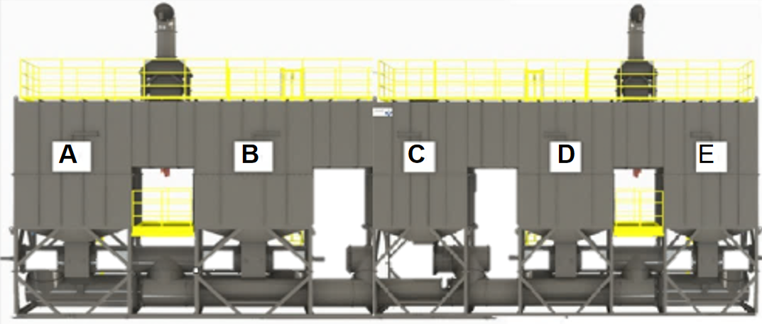
2. Thermal Oxidation and Regenerative Heat Recovery The five-chamber RTO uses the same basic thermal oxidation principle as a conventional RTO. Its treatment process combines exhaust gas preheating, high-temperature oxidation, and regenerative heat recovery.
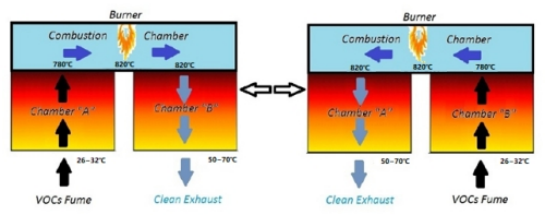
2.1 Exhaust Gas Preheating After pretreatment, VOC-laden exhaust gas enters the designated regenerative chamber. As it passes through the ceramic heat-storage media, the gas absorbs heat retained from the previous operating cycle. This process raises the exhaust gas temperature before it enters the combustion chamber, reducing the additional energy required for heating. 2.2 High-Temperature Oxidation After preheating, the exhaust gas enters the combustion chamber, where it is heated to the required oxidation temperature. Under controlled operating conditions, VOCs are oxidized into carbon dioxide (CO2) and water vapor (H2O). The combustion chamber provides the high-temperature environment required for VOC destruction. 2.3 Regenerative Heat Recovery After thermal oxidation, the high-temperature treated gas passes through another regenerative chamber. The ceramic heat-storage media absorbs thermal energy from the treated gas before it is discharged. During the next operating cycle, the stored heat is transferred to incoming exhaust gas, preheating it before it enters the combustion chamber. By repeatedly alternating between heat absorption and heat release, the system recovers thermal energy and helps reduce supplementary fuel consumption.
3. Central Purge Chamber and Residual Gas Collection The central C chamber is a key component of the five-chamber RTO design. It provides a shared purge function for both the AB and DE sections and collects residual exhaust gas from the bottom switching valve cavities during the switching process. 3.1 Purging Between Regenerative Chambers During operation, residual untreated exhaust gas may remain inside a regenerative chamber after its inlet stage. Before the chamber switches to the treated gas outlet stage, the purge process helps remove the residual gas to reduce the risk of untreated VOCs entering the treated gas discharge path. The shared C chamber provides the purge space required for this process, serving both regenerative chamber sections.
3.2 Residual Gas Collection During Valve Switching Another important function of the central C chamber is to collect residual exhaust gas trapped inside the bottom switching valve cavities. During valve switching, a small amount of exhaust gas may remain inside the valve cavity. Instead of allowing this residual gas to enter the treated gas discharge path, the system directs it into the central C chamber.
The collected gas is then gradually conveyed through a negative-pressure pipeline back to the RTO inlet, where it re-enters the treatment process and undergoes thermal oxidation. This design helps: Collect residual exhaust gas during valve switching. Reduce the risk of VOC carryover into the treated gas outlet. Return collected exhaust gas to the treatment process. Support stable and continuous VOC treatment. By combining chamber purging with valve cavity residual gas collection, the central C chamber provides an additional level of process control in the five-chamber RTO system.
4. Five-Chamber RTO Operating Sequence The five-chamber RTO follows three main operating stages: startup and temperature rise, normal operation, and controlled shutdown. 4.1 Startup and Temperature Rise During startup, the exhaust gas inlet valve remains closed, while the fresh air valve is opened. The system first uses fresh air to purge the RTO before the burner is ignited. After the initial purge, the burner automatically starts heating the system. The temperature rise follows a staged process: The RTO operates with a relatively low airflow during the initial heating stage. The burner gradually raises the temperature to the required process level. Once the temperature increases, the airflow is raised in stages. After reaching the specified operating temperature, the system enters standby mode and waits for exhaust gas introduction. This staged heating sequence helps the system reach its operating temperature under controlled conditions.
4.2 Normal Operation: ABC Chamber Cycle Taking the ABC chamber sequence as an example, the normal operating process involves exhaust gas preheating, thermal oxidation, heat recovery, and coordinated valve switching. Step 1: Exhaust Gas Preheating The emergency bypass valve is closed, the exhaust gas treatment valve is opened, and the fresh air valve is closed. After pretreatment through an alkaline spray scrubber, the VOC-laden exhaust gas enters regenerative chamber A. As the gas passes through the ceramic heat-storage media, it is preheated to approximately 750–800°C. Step 2: High-Temperature Oxidation The preheated exhaust gas enters the combustion chamber, where organic compounds are thermally oxidized. With the assistance of supplementary fuel, the combustion temperature is maintained at approximately 816–850°C, allowing the VOCs to decompose into carbon dioxide and water vapor under the specified operating conditions. Step 3: Heat Recovery After oxidation, the high-temperature treated gas enters regenerative chamber B. The ceramic heat-storage media absorbs thermal energy from the treated gas before it is discharged, storing heat for the next operating cycle. Step 4: Purging Before Switching As the switching time approaches, the linkage valve located below the central purge chamber C opens first. The residual exhaust gas collected during the switching preparation process is directed into chamber C. This step helps prevent residual untreated gas from entering the treated gas discharge path during the subsequent switching operation. Step 5: Automatic Valve Switching When the programmed switching time is reached, the automatic control system initiates the switching sequence. The inlet valve of regenerative chamber B opens, while the exhaust gas inlet valve of chamber A closes. After the switching operation is completed, the linkage valve below chamber C returns to its designated operating position, allowing treated gas to be discharged through the exhaust stack. The regenerative chambers then continue their alternating operating cycle.
4.3 Controlled Shutdown During shutdown, the system follows a controlled sequence to safely transition out of normal operation. The main operations include: Opening the emergency bypass valve. Closing the exhaust gas treatment valve. Opening the fresh air supply valve. Keeping the fan running to cool down the system. Stopping the burner. Continuing fresh air ventilation until the furnace temperature reaches the specified safe level. Stopping the fan and shutting down the system. This controlled shutdown sequence helps manage the temperature reduction and airflow transition inside the RTO.
5. Automated Switching Valve System The five-chamber RTO uses a dedicated pneumatic switching valve system to control airflow between the regenerative chambers. The switching valves are driven by pneumatic cylinders and operate according to commands from the RTO control system. By changing valve positions, the system redirects gas flow through the designated regenerative chambers during each operating cycle. The automated valve control system coordinates the switching sequence with the central purge chamber, allowing exhaust gas intake, treated gas discharge, and residual gas collection to take place according to the programmed operating logic. This coordinated control enables the regenerative chambers to alternate between their respective operating functions.
Conclusion The five-chamber RTO combines two independently operating regenerative chamber sections, AB and DE, with a shared central purge chamber C. While the regenerative chambers perform exhaust gas preheating and heat recovery around the thermal oxidation process, the central C chamber provides a shared purge function and collects residual exhaust gas from the valve cavities during switching. The collected residual gas is gradually returned to the RTO inlet through a negative-pressure pipeline for further treatment, helping reduce VOC carryover into the treated gas discharge path. Through coordinated chamber operation, residual gas collection, and automated pneumatic valve switching, the five-chamber RTO provides an integrated approach to VOC treatment and regenerative heat recovery.
Need help with industrial air pollution control?
AuSSE engineering can support VOC treatment, dust collection and filtration system planning for your facility.
Contact our engineering team